An introduction to the CAN bus: the basics and how it works
The Controller Area Network (CAN bus) is a message-based protocol built so that the electronic control units in a vehicle, and in other equipment, can communicate reliably and by priority. It lets a large number of control units talk to each other without a central computer and without wiring each one to every other. Bosch developed it in 1983, and it is still central today.
Where the CAN bus is used
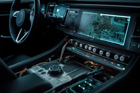
The CAN bus has proved indispensable in the automotive industry, where it carries the communication between the many electronic control units and sensors in a modern vehicle. Engine management, airbag systems, anti-lock braking and much else run over it.
Outside automotive, the CAN bus is used in other sectors too. Embedded systems in industrial automation, medical devices, aircraft, agricultural machinery and many other applications rely on the same reliability and efficiency.
The CAN bus and vehicle safety
The CAN bus is central to vehicle safety, because it is the network over which vehicle components talk to each other. It carries the data between control units and sensors, which is what makes effective control and monitoring of safety functions possible.
Reliable communication over the bus is essential, because faulty transmission of information can cause serious safety problems. It is worth stating plainly that the CAN bus is open to attack: it is part of a connected system and implements no security of its own. Appropriate measures are therefore needed to prevent unauthorised access and manipulation, for the sake of the occupants and of everyone else on the road.
Securing the bus means encryption and authentication techniques that keep the transmitted data intact and keep unauthorised parties out. It also means mechanisms for detecting and countering attacks on the bus.
How the CAN bus works
The structure of a CAN bus system
The system is built on two electrical lines, CAN high and CAN low. Data is transmitted through opposing charges, which reduces interference. Each participant (CAN node) sends messages to all the others, and identifiers control priority and recipient.
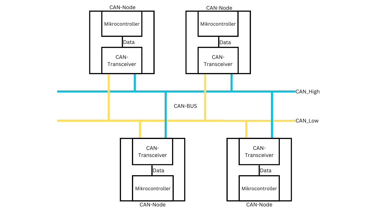
Fig. 1: schematic structure of a CAN bus with several nodes
The structure of CAN frames
CAN frames carry the data in a Controller Area Network. They consist of several fields, each holding specific information. There are two kinds: the standard CAN frame and the extended CAN frame.
Standard CAN frame:
-
Start of frame (SOF): 1 bit, the start of a CAN frame.
-
Identifier (ID): 11 bits, the priority of the frame and the address of the sending node.
-
Remote transmission request (RTR): 1 bit, marks a data frame or a remote request frame.
-
Control: 6 bits, holds control information such as the data length code (DLC).
-
Data: 0 to 64 bits, the transmitted data.
-
CRC (cyclic redundancy check): 16 bits, detection of transmission errors.
-
Acknowledgement (ACK): 2 bits.
-
End of frame (EOF): 7 bits.
Extended CAN frame:
The extended frame widens the identifier to 29 bits, which allows a larger address space.
-
Start of frame (SOF): 1 bit, the start of an extended CAN frame.
-
Extended identifier (XID): 29 bits, holding both the priority and the address of the sending node.
-
Remote transmission request (RTR): 1 bit, marks a data frame or a remote request frame.
-
Control: 6 bits, including the data length code (DLC).
-
Data: 0 to 64 bits, the transmitted data.
-
CRC (cyclic redundancy check): 15 bits, detection of transmission errors.
-
Acknowledgement (ACK): 2 bits.
-
End of frame (EOF): 7 bits.
The variants of the CAN bus
-
Low-speed CAN:
-
For fault-tolerant systems with low update rates.
-
Used in automotive for diagnostics, controls and displays.
-
Maximum data rate 125 kbps.
-
Example: comfort electronics such as window lifts.
-
-
High-speed CAN:
-
For communication between important subsystems with high update rates.
-
Data rates from 1 kbit to 1 Mbit per second.
-
Example: safety-related electronics such as ABS.
-
-
CAN FD (flexible data rate CAN):
-
Flexible data rates, for more data per message and faster transmission.
-
Data length raised to 64 bytes, maximum data rate 8 Mbps.
-
Not backward compatible.
-
What the CAN bus does well
-
Maintainability: diagnostics, data recording and configuration are straightforward.
-
Efficiency: prioritising frames gives the highest-priority data immediate access to the bus.
-
Robustness: it withstands electrical noise and electromagnetic interference.
-
Straightforward implementation: a proven standard with extensive support around it.
Where it falls short
-
No security built in: CAN bus systems are open to attack, because they provide no security mechanisms of their own.
-
Limited data rate: even with CAN FD the maximum is 8 Mbps.
Where the CAN bus stands
The CAN bus is in wide use across automotive, industrial automation, robotics, aerospace and other sectors. Its performance and reliability are why it became the default choice for this kind of data communication, and CAN FD, with flexible data rates and faster transmission, extends what it can do.
It also underpins the development of autonomous vehicles, carrying the communication between the sensors and control units those systems depend on.
The weaknesses are real too. The limited data rate and the absence of built-in security are problems in a world that keeps adding connectivity and data. Mechanisms for defending the CAN bus against attack are what mitigate the second one.